EPA’s video about the history and redevelopment of this Brownfield site.
Introduction
Recently, 3 Horizontal Remediation Wells were installed in lieu of 39 vertical air sparge (AS) / soil vapor extraction (SVE) wells which provided a more cost-effective and efficient remedial solution contributing to a riverfront brownfield redevelopment project. Using Horizontal Remediation Wells (HRWs) increased the total amount of well screen in contact with the contaminated zone by over 300% and had the added benefit of minimizing site disruption during remedial construction.
Background
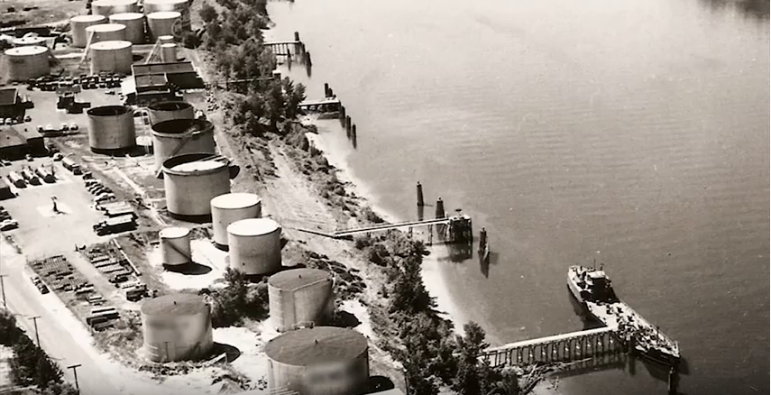
A college campus in East Hartford, Connecticut planned an infrastructure expansion which encompassed an approximately three-acre adjoining parcel. The site was a former a bulk petroleum products terminal for decades prior to redevelopment. Up to 13 above ground petroleum storage tanks previously encompassed the site contributing to significant subsurface contamination.
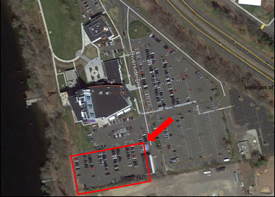
The redevelopment plan for the adjacent parcels was for additional parking for students and faculty. The environmental consultant retained by the college delineated the subsurface petroleum hydrocarbon impacts, which was present beneath a large portion of the lot. The dissolved petroleum plume threatened surface water of the nearby river.
Remediation Technology Selection
As part of cleanup through an EPA Brownfields assessment and remediation grant, the consultant performed a feasibility study and selected vertical AS/SVE technology as the site remedy. AS/SVE technology performs much of the “volatile organic compound (VOC)-related heavy lifting” in the environmental remediation industry.
Initial Remedial Plan
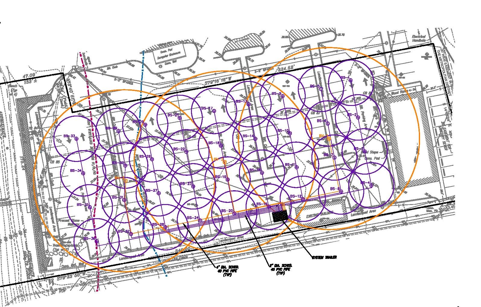
The original remedial design consisted of 39 vertical wells: 36 AS with 5 feet of screen per well for a total of 180 feet of AS screen and three SVE wells with 10 feet of screen per well for a total of 30 feet of SVE screen – covering an impacted area roughly the size of a football field.
Vertical Design Challenges and Disadvantages
The 39 vertical wells were to be connected to the surface treatment system via an extensive subsurface piping system. The piping system installation would require the excavation of hundreds of feet of trenching through the new parking lot and then repaving the entire parking lot. The parking lot would be unavailable for at least a month during the remedial construction, greatly disrupting college operations at an institution catering to commuting students.
Final Remediation Strategy
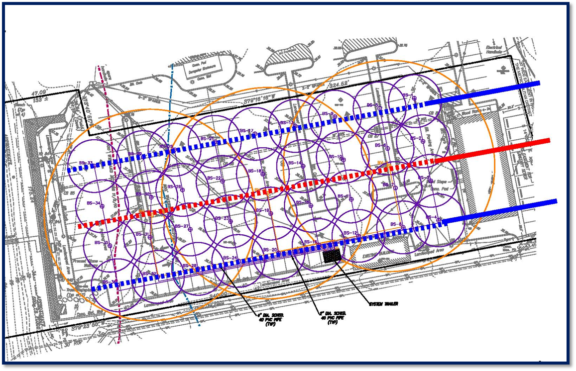
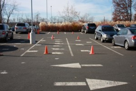
Based on proven results over the last two decades, remediation professionals are routinely deploying AS/SVE technology using the efficiency, power, and flexibility of HRWs. The consultant asked Directional Technologies, Inc. (DTI) to engineer and implement a horizontal design consisting of three blind completion HRWs: two AS wells each 450 feet long with 250 feet of screen for a total of 500 feet of screen and one SVE 450 feet long with 250 feet of screen. As noted above, DTI executed the HRW installation during a two-week period in December 2013. The parking lot remained operational during the HRW installation process except for the temporary loss of about a dozen parking spaces required for DTI’s drilling equipment footprint. There was minimal parking lot impact from drilling operations – patching of three well entry points measuring approximately two feet wide by four feet long. The wells were constructed of 3-inch diameter Schedule 80 polyvinyl chloride (PVC) pipe with PVC screens engineered by DTI to ensure uniform flow across the entire screen length.
Key Factors in Design
The final horizontal system increased the total amount of screen in contact with the contaminated zone from 210 feet of vertical screen to 750 feet with the horizontal design, a 357% increase. Additionally, blind horizontal installation method was utilized so that exit points for the wells were not required, further minimizing site disruption.
Conclusions
- The horizontal system placed over three times as much well screen within the target treatment area.
- The horizontal wells were installed from the adjacent parking lot to the east, so that the parking area was not impacted by drilling.
- The horizontal remediation wells were a significant contributor to the remediation of the southwestern portion of the site.
- Directional Technologies is proud to be a contributor to the successful redevelopment of this brownfield site.
References: Zuvic Carr & Associates, Brownfields redevelopment online video.