Challenge
Electrical Resistance Heating (ERH) was the selected remedial approach to address a DNAPL plume of tetrachloroethylene (PCE) and trichloroethylene (TCE) originating from former dry cleaning operations. Chlorinated solvents extended onto an adjacent property beneath an active manufacturing facility. ERH implementation with conventional vertical electrodes was cost prohibitive and disruptive to facility operations. Horizontal ERH electrodes were installed to minimize disruptions while effectively remediating impacts beneath the facility within a shorter duration.
Approach
In addition to disrupting facility operations, vertical ERH electrodes posed challenges to implementation within an active manufacturing facility. Dust generation during proposed vertical drilling activities within the facility would affect the manufacturing process. Limited access within the facility generated gaps in coverage with the proposed vertical ERH electrodes. A horizontal ERH electrode was designed and installed beneath the facility. Vertical ERH electrodes were installed in the source area where access and disruption did not pose issues. The ERH process extracted chlorinated solvents by heating the subsurface and capturing the resulting vapors with a vapor recovery system. Both the horizontal and vertical electrodes were designed to operate as a single system while covering the treatment area.
Horizontal Electrode Fabrication
Horizontal Solution to Electrode Placement
Electrical resistance heating electrodes are distributed in the subsurface to create a network of triangular electrode groupings in cross section. The purpose of such a configuration is to optimize distribution of heat across the target zone, from top to bottom. One set of electrodes is placed at a shallow horizon within the target zone, and another set is placed at a deep horizon. Shallow and deep electrodes are staggered, so as not to over lie each other.
Vertically, the target zone reaches from 2 to 15 feet bgs. However, the horizontal footprint spans a 17,000 sq.ft. area of the building. Electrodes are placed at only two different elevations, but multiple electrodes are placed along a given horizontal traverse.
Installing electrodes within horizontal casings is therefore much more efficient than installing them in vertical casings. The flexibility of shifting electrodes within a horizontal casing that extends 200 feet across the building is an additional benefit of installing electrodes horizontally. This flexibility optimizes electrical resistance heating in the course of its operation, as some portions of the target zone remediate more quickly than others.
Horizontal Electrode Benefits
- Placement of electrical resistance heating electrodes within horizontal carbon steel pipe overcame concerns about traditional, vertically installed electrodes at the site.
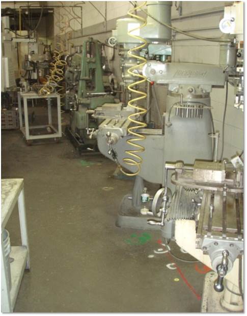
- Drilling inside of the active facility would generate dust and cause vibration that would interfere with the precision machining and manufacturing work performed in the building
- The labyrinthine distribution of multiple milling machines of many different shapes and sizes would interfere with vertical drilling work to install the ERH electrodes under the building
- Interruption of the non-stop, 24-hour-a-day production schedule was unacceptable to the owners of the operation, who were not responsible for the plume beneath the building because it emanated from a neighboring former dry-cleaning facility
- A grid of vertical ERH electrodes would severely limit placement options for a horizontal soil vapor extraction (SVE) system that was required in order to prevent vapors generated by the ERH system from entering the indoor air of the manufacturing facility.
Results
- Real-time, three-dimensional monitoring and analysis was used to confirm the design bore path for the horizontal ERH electrode
- Unknown building features, bedrock irregularities and historic fill were encountered
- Advancement of the horizontal ERH electrode was achieved with horizontal directional drilling (HDD) technology
- Stresses on the electrode material including drilling pressures and bend radius were monitored real-time to ensure no adverse effects
- ERH system was started and monitoring data included energy use, temperature and contaminant concentration reductions
- Horizontal ERH electrode resulted in higher efficiencies and chlorinated solvent reductions in comparison to the vertical ERH electrodes
Precision Equipment within Active Manufacturing Plant
Hybrid ERH and Horizontal SVE Wells
- Shallow ERH pipes served double duty as horizontal soil vapor extraction (SVE) wells
- Alternating sections of pipe were slotted for SVE, or solid for ERH
- This configuration avoided logistical problems of threading SVE wells into network of ERH electrodes.
Horizontal Electrode Installations
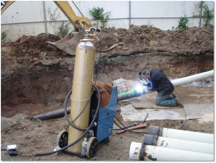
- Heavy, rigid black steel casing with 6-inch diameter was used for installing the horizontal ERH system
- Horizontal electrodes were installed with both blind and entry-exit methods for the ERH system
- Each black steel casing section was welded onto the casing string as it advanced into the wellbore
- Shallow horizontal electrodes were only 3 feet below the building slab, so drilling method was adapted to minimize communication through cracks in the foundation
- Grout seal was emplaced around the horizontal electrodes where crossing below building foundation in order to prevent short-circuiting of horizontal SVE system
No Disruptions — or Loss of Revenue
Round-the-clock site operations using sensitive milling equipment continued uninterrupted by horizontal directional drilling to ensure successful and unobtrusive remedial system operation.