Horizontal Wells allow Rapid Clean-up of R&D Facility Gasoline Release
Background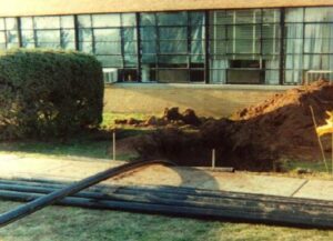

A Research and Development facility in central New Jersey released several thousand gallons of gasoline to the subsurface. Environmental investigations revealed that approximately 80% of the phase separated plume existed below the building. Uninterrupted operation and prevention of vapor intrusion in the facility were key factors that dictated an alternative approach to the remedial strategy. Hudson Environmental Services, Inc. of Matawan, New Jersey completed the remedial investigation, assessed remedial alternatives and proposed a remedy. Horizontal soil vapor extraction and horizontal air sparge with vapor treatment utilizing catalytic oxidation was the recommended and selected remedy.
The Challenge Presented
Two technical approaches were available for the horizontal soil vapor extraction and horizontal air sparge system orientation: install a series of multiple vertical wells (a number would be required inside the building) with an interconnecting subsurface piping network, or install three horizontal wells, which would pass beneath the building. Feasibility and financial analyses indicated that the horizontal well system would not disrupt business operations, be less expensive and more efficient than the traditional vertical well approach. Directional Technologies, Inc. was engaged to install the horizontal wells.
Directional Technologies at Work: Our Solution
Pilot testing and subsurface characterization provided data enabling Directional Technologies to design two horizontal air sparge wells and one horizontal soil vapor extraction well. The horizontal air sparge and horizontal soil vapor extraction wells were designed to operate at 250 cubic feet per minute (CFM). The system design included a catalytic oxidizer to destroy hydrocarbon vapors extracted from the horizontal soil vapor extraction well. The NJ Department of Environmental Protection (NJDEP) approved the remedial design following the first design submittal. Underground utilities, building footings and other subsurface structures were identified and surficially marked out prior to well installation. Directional Technologies designed the horizontal well trajectories to avoid these buried structures.
Directional Technologies used a Ditch Witch Directional Boring System to directionally drill the horizontal wells and has used this drill rig to successfully drill bores up to 12 inches in diameter and 700 feet long; while compact in size, it is extremely powerful. The directional drill rig’s compact size allows it to be used in relatively confined areas and the rubber tracks exert minimal ground pressure, minimizing risk of damage to pavement and turf. The power and two speed spindle rotation capability enabled the rig to successfully penetrate both hard and soft soil conditions encountered at the site (fine sands, silts and clays).
Directional Technologies advanced each pilot hole to the specified depth and horizontal termination point using a spade bit. Drill bit X-and-Y axis directional control and operational temperature was provided by a hand-held surface walk-over radio detection instrument. The instrument receives continuous radio signals from a battery-powered instrumentation module contained in a length of drill pipe located directly behind the drill bit. Regularly measuring drill bit temperature is important to ensure that drilling fluids are circulating through the drill bit, especially when drilling in rock.
Directional Technologies enlarged each pilot hole to a diameter of 6.5 inches using a spiral-cutting-configured back reamer drill bit designed to minimize formation displacement and compaction. Cement grout pumped through tremie pipes formed a seal in the annular space between the riser and formation. Directional Technologies developed the horizontal wells with water and a proprietary additive to flush out drilling fluid that may have entered the formation during the horizontal drilling process. Directional Technologies installed two identical horizontal air sparge wells configured as follows: 4 inch diameter, riser length: over 500 feet, screened interval: 260 feet, installed depth: 22 feet below ground surface, 7-9 feet into the water table. The single horizontal soil vapor extraction well was configured and installed as follows: 4 inch diameter, riser length: over 480 feet, screened interval: 240 feet, installed depth: 8 feet below ground surface (5-7 feet above the water table). The horizontal wells were constructed of SDR-11, a high density polyethylene (HDPE) product; Directional Technologies validated the choice of this choice product via detailed computer modeling. Modeling further dictated the need for multiple slot-zones in the horizontal soil vapor extraction well screen due to the multiple design goals of uniform air sparging and extraction and a flow rate of 250 CFM to the catalytic thermal oxidizer.
Results that Reward
The time required to achieve site remediation can be conservatively calculated from the quantity of oxygen delivered to the site by the remediation system. Directional Technologies designed/installed each horizontal air sparge well to deliver approximately 2 pounds per minute of oxygen to the subsurface, or a total of 4 pounds per minute. At this oxygen delivery rate Directional Technologies estimated that site cleanup would be accomplished in approximately one year. The horizontal air sparge and horizontal soil vapor extraction system operated from March 1999 to October 2000 and removed approximately 17,000 pounds of gasoline. The separate phase gasoline plume under the building was completely eliminated. This resulted in the NJDEP approving” no further action” for soils.