Challenge
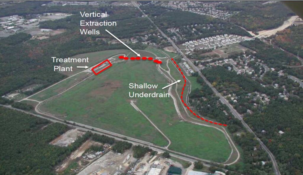
Vertical wells at the landfill required individual submersible pumps, water level controls, flow meters, and force mains. Each vertical well suffered from mineral deposits, incrustation, and sediment buildup over the years.
Former Groundwater Extraction System Layout
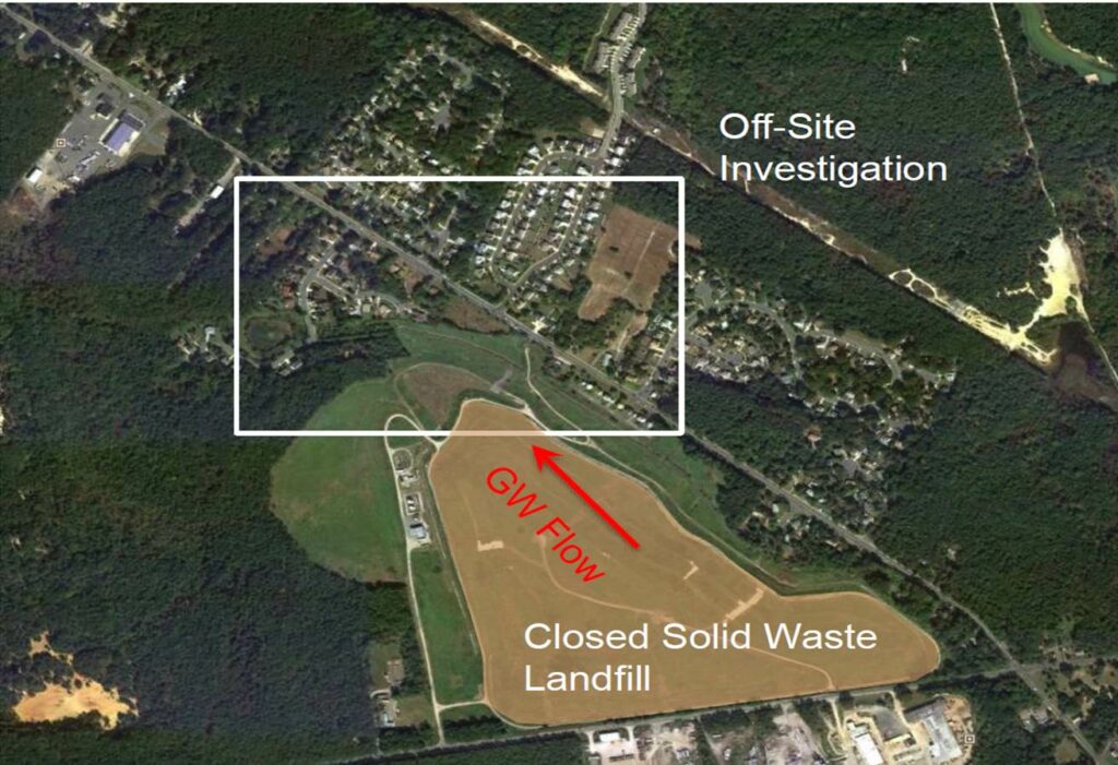
It is relatively common for older, unlined landfills to negatively impact the downgradient groundwater quality, even if they have been capped. These impacts often produce a definable groundwater plume characterized by typical leachate-related constituents such as elevated chlorides and TDS, and low pH. More often than not, the plume also contains elevated chlorinated volatile organic compounds (VOCs) that are either contained in household waste in small amounts or discharged into the landfill in larger quantities. Large concentrations of volatile and semi-volatile organics are more common downgradient of older solid waste landfills.
Off-Site Groundwater Investigation
A typical design of a downgradient containment system includes groundwater modeling to identify the number, location, and pumping rate of vertical extraction wells that are necessary to capture the plume.
Approach
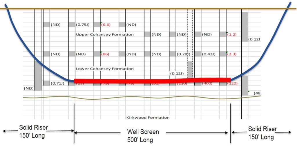
A line of vertical extraction wells was installed and operated at a landfill in the northeastern United States for over 8 years. However, due to the fine-grained nature of the soils and the relatively thin saturated zone, maintenance of the extraction wells had proven time-consuming and costly. To alleviate these issues, and to address a more refined understanding of the off-site extent of the plume, a 500-foot long horizontal extraction well was designed and installed at the landfill. The horizontal well targeted the lower portion of the formation containing the most elevated concentrations of chlorinated solvents.
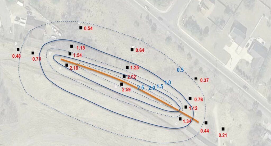
1,4-Dioxane Plume (ppb) @ 38 feet bgs
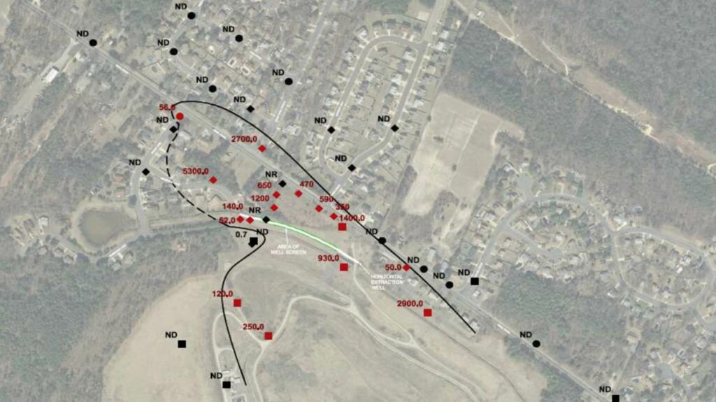
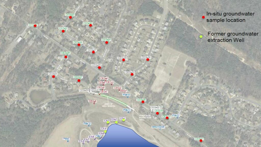
Off-Site Groundwater Sample Locations
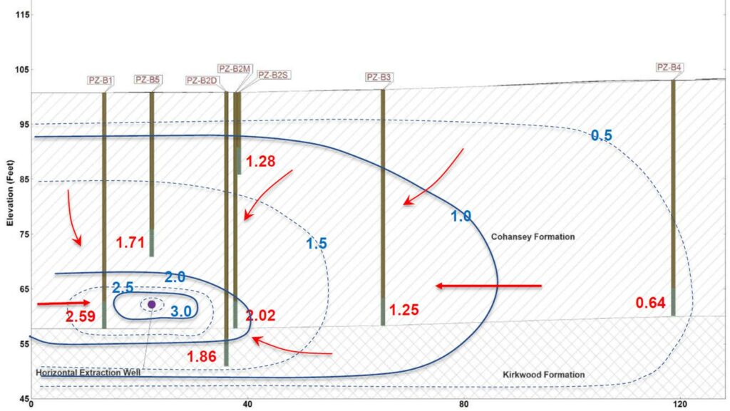
Site Stratigraphy
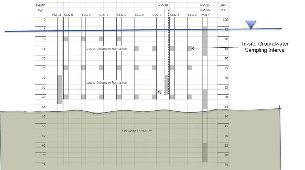
Horizontal Extraction Well Cross-Section
Horizontal Extraction Well Layout
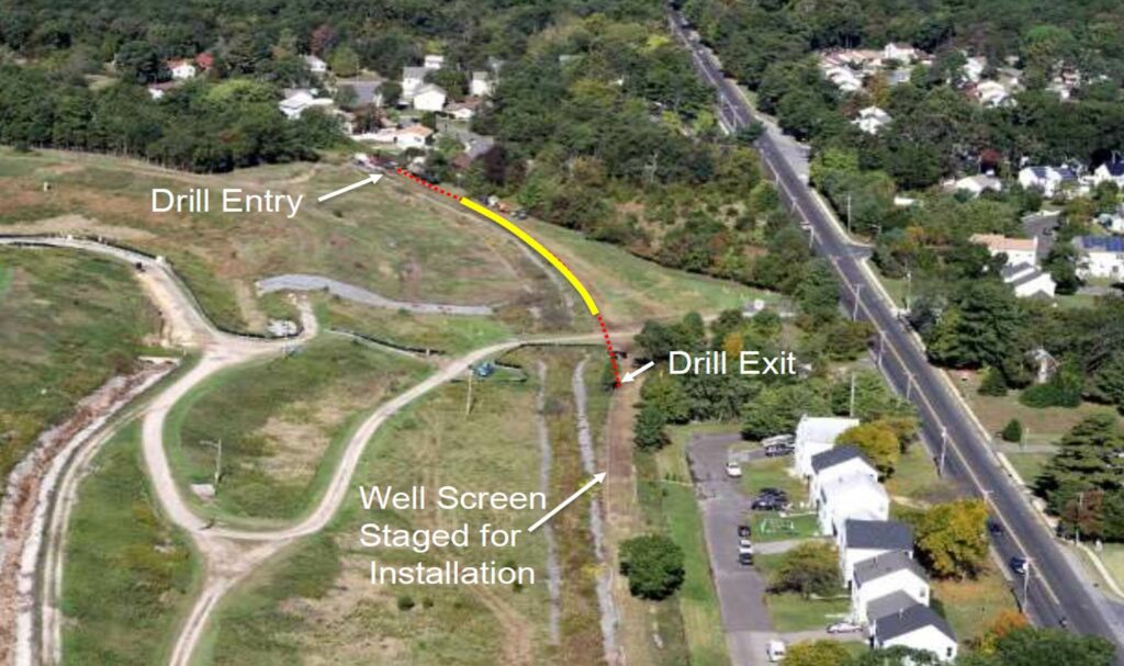
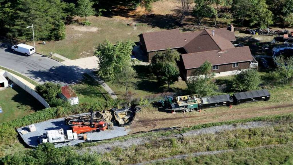
Drone Flyover of Horizontal Staging Area and Drill Entry
Results
The horizontal well created a uniform, continuous capture zone with only one pump and minimal controls. With the horizontal well screen completely submerged, less iron fouling occurred and the pump did not cycle on and off. Installation and operational costs were compared between the two systems. Actual capture zone data was also analyzed and compared to the predicted capture zone for the horizontal well.
Drawdown After 24-Hour Pump Test
PDF: Using Horizontal Extraction Wells to Contain Chlorinated Compounds Near Landfills